Equipment Racks: Transitional
Newton's Seismic Unequal Flange Equipment Racks
The Transitional UFER is a seismically rated Unequal Flange Equipment Rack which can be configured as a standard UFER or Network bay by choosing the appropriate front guard rail at time of order. Several ordering options are available including open or closed duct, various height options in 19″ or 23″ widths and optional top angle. Mounting hole patterns are available in EIA WIde, EIA Universal, WECO
Newton 's 7′–0″seismic Transitional UFER meets the earthquake criteria (Seismic Zone 4) of Telcordia document GR-63-core when loaded with 500 pounds to simulate rack mounted equipment.
UFER configuration
This is the standard UFER with a redesigned upright to remove the return flanges, giving a little more room for inter bay wire harnesses. It also has a one piece base cover allowing easier access for installation. The 1st mounting hole in a SUFER starts at 7″ from bottom of frame.
Network Bay configuration
This is the standard Network Bay with a redesigned upright to remove the return flanges, giving a little more room for inter bay wire harnesses. It also has a one piece base cover allowing easier access for installation. The 1st mounting hole in a Network Bay starts at 5″ from bottom of frame.
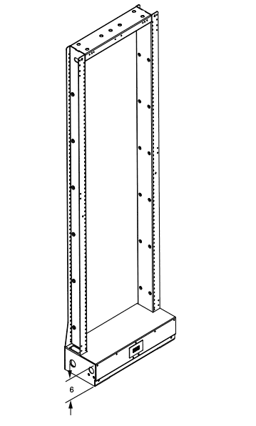
Closed Duct Transitional UFER Illustration
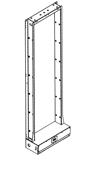
Open Duct Transitional UFER Illustration
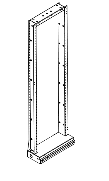
Closed Duct Transitional Network Bay Illustration
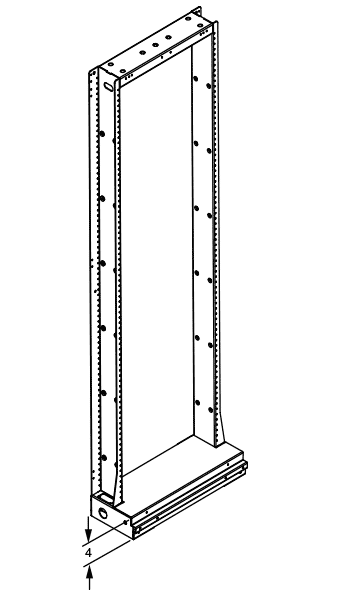
Open Duct Transitional Network Bay Illustration
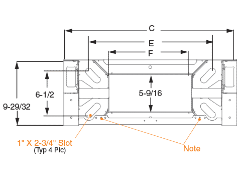
Transitional Footprint
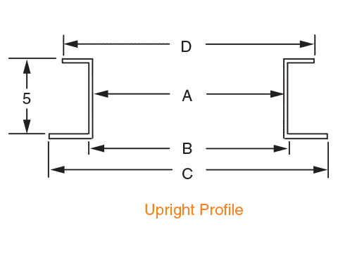
Transitional Upright Profile
Notes
- Available in closed duct (wide flange on guard rail side to the front) or open duct (narrow flange on guard rail side to the front) versions. Open duct with EIA wide spacing shown.
- Front Guard Rail is provided
- Four 2″ square washers are included with seismic versions.
- Provision for attachment of user-provided two-hole grounding lug.
- Provision (three weld nuts) for attachment of user-provided 5/8″ threaded rod.
- For 7′-0″; and 7′-6″ racks with a top angle, subtract one mounting space from that shown for 7′-0 and 7′-6″ rack without a top angle
- Base mounting pattern (refer to section a-a) meets the criteria of GR-63-core, figure 2-1b.
- Rack must be secured to concrete floor using seismic floor mounting kit (222128xxxx, 004615xxxx or equivalent). Installing this rack in any other manner may impact load capacity and seismic performance.
Table below shows complete part numbers for a limited selection of SUFERs . Newton has several SUFER configurations to fit your application, contact your Customer Service Representative for other height and mounting options
| Part Number | A | B | C | D | E | F | Rack | Duct | Hole Pattern | Mounting Spaces | Height |
|---|---|---|---|---|---|---|---|---|---|---|---|
| 0080360130 | 21-1/2″ | 22-5/16″ | 25-7/8″ | 23-7/8″ | 18-7/64″ | 12/3/8″ | 23″ UFER | open | EIA Wide | 42 | 7′-0″ |
| Part Number | A | B | C | D | E | F | Rack | Duct | Hole Pattern | Mounting Spaces | Height |
|---|---|---|---|---|---|---|---|---|---|---|---|
| 0080700130 | 17-1/2″ | 18-5/16″ | 21-7/8″ | 19-7/8″ | 14-7/64″ | 8/3/8″ | 19″ Network Bay | closed | 1″ | 76 | 7′-0″ |
| 0080710130 | 17-1/2″ | 18-5/16″ | 21-7/8″ | 19-7/8″ | 14-7/64″ | 8/3/8″ | 19″ Network Bay | closed | EIA Wide | 44 | 7′-0″ |
| 0080800130 | 21-1/2″ | 22-5/16″ | 25-7/8″ | 23-7/8″ | 18-7/64″ | 12/3/8″ | 23″ Network Bay | closed | 1″ | 76 | 7′-0″ |
| 0080810130 | 21-1/2″ | 22-5/16″ | 25-7/8″ | 23-7/8″ | 18-7/64″ | 12/3/8″ | 23″ Network Bay | closed | EIA Wide | 44 | 7′-0″ |
| 0080850130 | 21-1/2″ | 22-5/16″ | 25-7/8″ | 23-7/8″ | 18-7/64″ | 12/3/8″ | 23″ Network Bay | open | 1″ | 76 | 7′-0″ |